TL;DR: Pneumatic grippers and vacuum suction cups are the two dominant end-of-arm tooling choices for servo take-out robot arms in plastic injection molding, and the right choice depends on part geometry, weight, surface finish, and production volume. Pneumatic grippers use compressed air at 5–7 kgf/cm² to actuate mechanical fingers that clamp solid parts with positive force—reliable for parts over 100g with defined grip lands. Vacuum suction cups require no mechanical fixturing, work on flat or lightly contoured surfaces, and are the default choice for thin-walled containers and cosmetic parts where mechanical contact would leave marks. Because servo take-out robots like the SPRT3S series use X/Y/Z AC servo motors for all three motion axes, the tooling choice directly affects the minimum take-out time and the robot’s ability to sustain a sub-2-second cycle under continuous production conditions.
How Servo Take-Out Robots Work in Injection Molding
A servo take-out robot arm extracts a molded part from the open mold cavity and transfers it to a conveyor, packaging station, or quality inspection fixture. Unlike older pneumatic take-out systems—which use cylinder-driven motions with fixed stroke lengths—servo take-out robots use AC servo motors on all three principal axes: vertical (Z), horizontal transverse (X), and horizontal cross-wise (Y). This servo architecture gives the robot programmable, variable-speed motion with accurate positional control at any point in the stroke, enabling smoother acceleration profiles, faster cycle times, and more precise part placement than legacy pneumatic systems. In ROBOT (Ningbo) Intelligent Technology’s SPRT3S product line, established since 2004, the servo motors drive an X,Y,Z coordinate motion system with a telescopic-type arm. The transverse stroke ranges from 920 mm in the smaller SPRT3S1000W model to 2,200 mm in the SPRT3S4200W, while the vertical stroke extends from 1,030 mm to 4,200 mm depending on the model. This dimensional flexibility is why servo take-out robots are specified for injection molding machines ranging from 160 tonnes all the way up to 4,500 tonnes clamping force, covering the full range of commercial injection molding equipment. The minimum take-out time—the cycle time from robot enter to robot extract—is a function of the robot arm’s servo motion profile, the part’s weight, and the tooling type. For the 3 kg maximum payload SPRT3S1000W model, the minimum take-out time is 0.7 seconds; for the 6 kg payload SPRT3S1100W, it is 1.6 seconds; and for the 25 kg payload SPRT3S1600W, it reaches 1.7 seconds. Because the servo drive system allows the robot to accelerate and decelerate smoothly along programmed velocity profiles, the take-out time is limited more by the part inertia and the tooling’s response time than by the robot mechanics themselves. The robot’s drive system also deserves attention in the context of tooling selection. All SPRT3S models use X,Y,Z AC servo motor drives operating at 5–7 kgf/cm² working air pressure, with power supplies ranging from AC220V single-phase for the smaller models to AC380V three-phase for the largest SPRT3S1600W and above. The three-phase power requirement for larger robots reflects the higher mechanical power needed to accelerate and decelerate heavier payloads within the same cycle time window.
End-of-Arm Tooling: The Critical Last Meter of the Automation Chain
End-of-arm tooling (EOAT) is the device attached to the robot arm’s wrist that actually interfaces with the molded part. It is the most consequential component in determining whether a take-out robot achieves its theoretical cycle time, and the choice between pneumatic gripper and vacuum suction is the first and most important tooling decision for any injection molding automation project. The EOAT must securely hold the part from the moment the robot enters the mold until it reaches the unload position, without deforming the part, without dropping it during acceleration or deceleration, and without marking or scratching the visible surfaces that the customer will see. It must also release the part cleanly at the unload position without residual holding force that would cause part ejection failures or misalignments on the conveyor or packaging fixture.
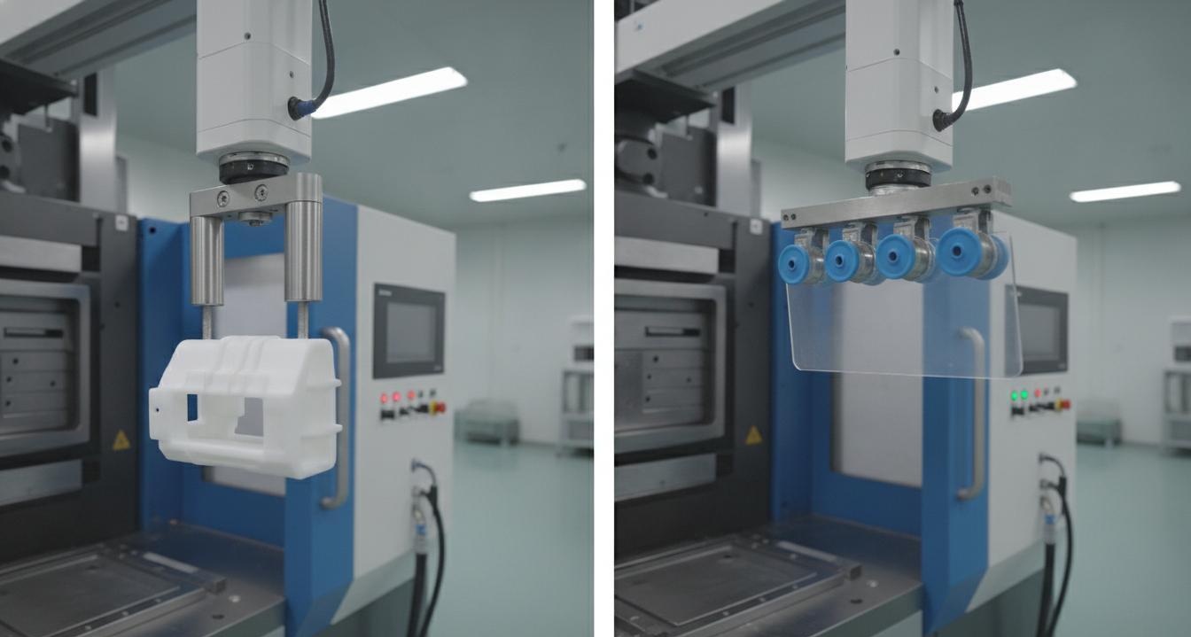
Pneumatic Gripper: Mechanical Clamping with Compressed Air
A pneumatic gripper uses a double-acting piston cylinder to drive two or more mechanical fingers toward each other, clamping the part between them. The working air pressure for industrial injection molding grippers is typically 5–7 kgf/cm² (approximately 70–100 psi), supplied from the plant compressed air system through a dedicated airline routed to the robot wrist. This is the same pressure specification as the SPRT3S robot’s own pneumatic system, which means the gripper can be powered directly from the robot’s existing air supply circuit without a separate pressure regulator or independent compressor. The grip force is determined by the cylinder bore size, the air pressure, and the finger lever ratio. For a typical two-finger parallel gripper used in injection molding, grip forces range from 100 N to 800 N per finger pair, depending on the cylinder specification. For the SPRT3S series robots, which operate at 5–7 kgf/cm² working air pressure, a standard industrial gripper delivers sufficient holding force for parts up to approximately 3 kg per grip zone without risk of part drop during robot extraction. For heavier parts, the SPRT3S1600W and above models provide the higher payload capacity needed to accommodate both the part weight and the gripper mass. Pneumatic grippers excel in four specific injection molding scenarios. The first is thick-walled solid parts with defined grip lands—parts such as bottle caps, automotive housings, technical components, and consumer electronics enclosures where the mold designer has specifically provided flat surfaces for the robot to grip. These parts can withstand the 50–200 N per finger contact force without deformation or surface marking. The second is parts with undercuts or complex 3D geometry that vacuum cups cannot seal against. A mechanical gripper finger can be shaped to engage an undercut in the molded part, providing positive retention that no vacuum cup can replicate. Because vacuum suction requires a continuous, flat or uniformly contoured sealing surface, so a part with deep ribs, internal threads, or recessed features can only be reliably extracted with mechanical grippers that engage the part’s geometry rather than its surface area. The third is high-speed extraction where maximum holding force is needed during rapid acceleration and deceleration phases of the robot motion. Pneumatic grippers respond to the air signal within 20–40 ms, and the clamping force is fully established within 50–100 ms of the signal onset. This response time is fast enough to be accounted for in the robot’s motion program. Vacuum systems require the vacuum generator to reach full negative pressure, which adds 100–300 ms of lag depending on the cup size and the vacuum generator displacement—a delay that can cause the part to drop during the critical first500 ms of extraction in high-speed cycles. The fourth is parts with internal cores or unsprung undercut features that require a specific, repeatable grip position. The gripper fingers can be custom-machined or 3D-printed from nylon or carbon-fiber-reinforced polymers to match the exact grip geometry of the specific part, providing a zero-play, repeatable interface that is resistant to alignment drift over millions of cycles. This custom finger capability makes pneumatic grippers the solution of choice for high-volume production runs where consistency across millions of cycles is the primary quality metric. The main limitation of pneumatic grippers is surface marking. For cosmetic parts—components where the visible surface must be free of gate blush, ejector marks, tool marks, or gripper contact marks—mechanical finger contact can create stress concentrations or visible surface deformation. In cosmetic applications, vacuum cups or specialized soft-touch silicone finger coatings are required.
Vacuum Suction Cups: Surface-Contact Holding for Cosmetic and Thin-Wall Parts
Vacuum suction tooling uses one or more elastomeric cups connected to a vacuum generator, which evacuates the cup interior to create a negative pressure differential relative to atmospheric pressure. The resulting holding force is proportional to the cup’s effective sealing area and the vacuum level achieved. A 50 mm diameter cup at 75% vacuum generates approximately 150–180 N of holding force—sufficient for parts between 50g and 2 kg with smooth, flat grip surfaces. Multiple cups can be combined to increase the total holding force for larger parts, though the robot’s payload rating must be reduced accordingly to account for the combined weight of the cup assembly, vacuum lines, and part. Vacuum suction cups are the preferred tooling choice for three categories of injection molded parts. The first is thin-walled containers and packaging items—yogurt cups, blister packs, cosmetic containers, medical device housings, and similar items where the wall thickness is typically 0.4–1.2 mm and the part is too flexible to survive mechanical clamping without deformation or wall collapse. Because vacuum cups distribute the holding force uniformly across the sealing area rather than at discrete contact points, so they grip thin-wall parts without creating local stress concentrations that would distort, crack, or dent the part. The second is cosmetic parts with high-gloss or textured visible surfaces where any mechanical contact would be immediately visible as a mark or blemish. A vacuum cup with a soft Shore A40–60 durometer elastomer cup—typically made from silicone, EPDM, or NBR rubber—can grip a high-gloss surface without leaving a visible impression, provided the cup material is compatible with the molded polymer and does not outgas or transfer additives onto the part surface. This is particularly critical in medical device molding and cosmetic packaging, where part contamination is a regulatory concern. The third is parts with large, flat grip surfaces that are specifically designed for vacuum extraction—often in clean-room or pharmaceutical packaging molding environments where the part must remain uncontaminated by any gripper materials or lubricants. Vacuum cups made from FDA-compliant silicone or medical-grade EPDM are widely used in pharmaceutical packaging, food-contact product molding, and clean-room medical device production. The primary limitation of vacuum suction is surface compatibility. The cup must seal against a smooth, non-porous surface; even a 0.5 mm draft angle on the molded part surface can prevent a vacuum cup from maintaining a seal during extraction, because the draft creates a gap between the cup lip and the part surface as the part releases from the core. Additionally, vacuum cups generate less holding force per unit of contact area than pneumatic grippers, making them unsuitable for heavy parts above approximately 2 kg unless multiple large-diameter cups are used simultaneously—which adds weight and complexity. The vacuum generator itself adds complexity and maintenance to the robot’s utility requirements. Most servo take-out robot installations include a dedicated vacuum pump or venturi ejector at the robot base station, with flexible tubing routed through the hollow robot arm structure to the wrist. Because the vacuum circuit adds compressible volume to the holding system, so the response time of the vacuum grip is slower than that of a direct-air pneumatic gripper, which is connected directly to the air supply without an intermediate volume chamber. In high-cycle applications below 4 seconds total cycle time, this response lag can become the binding constraint on achieving the target take-out time.
Hybrid and Multi-Technology Tooling Configurations
Modern injection molding production lines increasingly use hybrid tooling configurations that combine pneumatic gripper elements and vacuum suction cups on the same robot wrist. A common example is a container with a snap-lock lid: the pneumatic gripper holds the base component while a vacuum cup holds the lid, allowing the robot to demold both components in a single entry stroke and deliver them separately to downstream assembly or packaging stations. Another hybrid approach is the use of pneumatic gripper fingers with vacuum-assisted retention. In this configuration, mechanical fingers provide the primary grip geometry, while a small vacuum cup in the center of the finger set provides auxiliary retention that prevents the part from lifting off the fingers during high-acceleration extraction. This is particularly useful for large, flat parts such as automotive instrument panels, bumper fascias, or large-container lids, where the gripper fingers can only contact the part at its edges or gated end, leaving the central area free for the vacuum cup to engage. The choice of EOAT technology also affects the robot arm’s payload specification. The SPRT3S1000W with a 3 kg maximum payload rating must account for the combined weight of the EOAT device, the part, and any vacuum lines or airlines when calculating whether the 3 kg limit is exceeded. A vacuum cup tooling assembly with integrated generator can weigh 0.5–1.5 kg, which reduces the effective part weight capacity by the same amount.Because the robot’s payload rating is a hard mechanical limit, exceeding it causes servo overload faults, trajectory errors, and accelerated drive system wear, so the EOAT weight must be budgeted into the selection calculation before specifying the robot model.
Evaluating Cycle Time Impact: Which Tooling is Faster?
For a given part and molding cycle, the tooling choice affects three time components in the take-out sequence: the grip engagement time (time from robot wrist position to secure hold), the extraction time (determined by the robot’s servo motion profile and part weight), and the release time at the unload station. In terms of pure grip engagement speed, pneumatic grippers are faster—typically 50–100 ms from air signal to full clamp force. Vacuum systems add 100–400 ms depending on cup size and vacuum generator type. However, in terms of extraction speed, the analysis changes. Vacuum cups allow the robot to engage the part at the cavity surface without needing to fit fingers inside the mold cavity geometry, which can allow a shorter robot entry stroke for some part geometries where the cavity depth or internal core geometry restricts gripper finger insertion. Because the minimum clearance between the mold cavity geometry and the gripper fingers is often the binding constraint in achieving fast take-out cycles, a vacuum cup that requires no internal finger clearance can sometimes enable a shorter total robot stroke that more than compensates for the slower grip engagement time, particularly in deep-cavity thin-wall parts where no gripper finger geometry can fit without risking mold damage. For SPRT3S series robots, the minimum take-out time specification of 0.7 seconds for the SPRT3S1000W is based on the robot arm’s mechanical capability, not the tooling. In practice, the tooling selection and the part geometry determine whether this theoretical minimum is achievable on a given production part. Parts with simple flat geometry and adequate grip lands can typically achieve close to the rated minimum, while complex geometry parts may require longer take-out times to accommodate the gripper approach and extraction path.
Tooling Cost, Maintenance, and Production Floor Reality
Pneumatic gripper tooling has lower first cost and simpler maintenance than vacuum systems. A standard two-finger industrial gripper with cylinder, mounting bracket, and fingers costs $200–$800 depending on the brand, bore size, and grip force rating, and the only consumable is the air line filter element and the occasional seal kit for the cylinder. The maintenance interval for a pneumatic gripper in a clean injection molding environment is typically 12–24 months before seal replacement is needed. Vacuum cups cost $15–$60 per cup and have a finite service life measured in production cycles—typically 50,000 to 200,000 cycles depending on the elastomer material, the part weight, and whether the cups are used on soft or hard polymer surfaces. The vacuum generator, whether a rotary vane pump or a venturi ejector, requires annual maintenance including oil change or seal replacement for the pump, and periodic inspection of the vacuum lines for leaks or cracks.Because vacuum cup wear is often invisible until a part is dropped—a catastrophic failure event in high-volume production—a preventive replacement schedule based on cycle count rather than visual inspection is the recommended maintenance practice for vacuum tooling. On the production floor, pneumatic grippers are preferred in high-volume, low-mix operations where the same part runs for days or weeks at a time. The tooling setup is stable, the grip force is consistent, and the maintenance interval is predictable and calendar-based. Vacuum systems are more common in high-mix, lower-volume operations where changeover time dominates the production schedule—vacuum cup exchange is typically faster than gripper finger reconfiguration for different part geometries. Because gripper fingers must be physically repositioned or replaced to accommodate a different part geometry, so a tooling changeover on a pneumatic gripper system can take 30–60 minutes, whereas a vacuum cup changeover typically takes 5–15 minutes—a significant advantage in operations running multiple SKUs per shift.
Conclusion
The choice between pneumatic gripper and vacuum suction end-of-arm tooling for servo take-out robot arms in injection molding is not a binary one-size-fits-all decision—it is a geometry, weight, surface finish, and production volume trade-off that must be made for each part family. Pneumatic grippers are the reliable workhorse for solid parts with defined grip lands and high-cycle, high-volume production runs. Vacuum suction cups are the preferred solution for thin-walled containers, cosmetic parts, and high-mix operations where changeover speed matters more than raw grip force. Because servo take-out robots like the SPRT3S series deliver programmable, high-precision motion with minimum take-out times of 0.7–1.7 seconds depending on the model, so the EOAT selection should be made based on the part’s extraction requirements rather than the robot’s mechanical capability. The robot can handle the motion; the tooling must handle the grip. For specific SPRT3S series model selections, payload specifications, and dimensional data for your injection molding machine, visit the open-type servo take-out robot product page or explore ROBOT Ningbo’s complete automation product range for injection molding machines, auxiliary equipment, and whole-plant planning solutions.
About the Author: Mr. Chen is Technical Director at ROBOT (Ningbo) Intelligent Technology Co., Ltd., a position held since the company’s founding in 2004. With over two decades of experience in plastic injection molding automation, Mr. Chen has led the development of the SPRT3S servo take-out robot product line and the company’s whole-plant planning division for central feeding, water, and air supply systems. His focus is on real-world injection molding performance: cycle time optimization, production floor uptime, and the integration of robot arms with injection molding machines ranging from 160 to 4,500 tonnes clamping force.
Post time: Jun-08-2026