TL;DR — Key Takeaways
- Servo robot arms reduce injection molding cycle time by 15–30% by eliminating manual extraction delays (5–8 seconds/cycle recovered).
- Servo vs. hydraulic: servo offers better precision, energy efficiency, and lower maintenance; hydraulic offers high grip force for dirty environments.
- The 5 critical specs: extraction time, payload capacity, traverse speed, positional repeatability, and swing/reach envelope.
- Typical servo robot arm ROI payback: 6–12 months (labor saving + 15–25% production capacity gain).
- Most common failures: gripper mismatch, mold clearance interference, signal interface issues, and under-specifying payload margin.
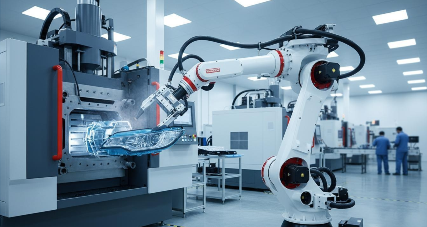
Every injection molding operation has the same fundamental constraint: the molding machine is the most expensive asset on the floor, and every second it sits idle waiting for a human to extract a part is a second of lost capacity. Yet in 2026, a significant percentage of injection molding operations globally still rely on manual part extraction—operators opening the mold, reaching in, pulling the part, and placing it in a bin—while the machine waits.
The math is straightforward. A 30-second molding cycle with manual extraction effectively becomes a 35–40 second cycle because the operator cannot be at the machine the instant it opens. Across a 10-hour shift at USD 50 machine hour rate, that 5–10 second per-cycle delay costs USD 140–280 in wasted machine time daily. A servo robot arm, properly selected and integrated, eliminates that wait state entirely—and typically pays back its acquisition cost within 6–12 months from recovered production capacity alone.
In this guide, I draw on 20 years of experience integrating servo robot arms into injection molding operations across Southeast Asia, the Middle East, and Europe to walk you through how servo robot arm automation actually reduces cycle time, how to select the right robot for your application, and how to avoid the integration failures that cause automation projects to underdeliver.
Why Servo Robot Arms, Not Hydraulic
The first decision in any injection molding automation project is choosing between servo and hydraulic robot arms. In 2026, servo is the dominant choice for new installations—but hydraulic still makes sense in specific environments.
Servo robot arms use electric servo motors for all axis drives, providing precise positional control, high energy efficiency, and clean operation with no hydraulic fluid. Per ISO 9283 (Manipulating industrial robots — Performance criteria and related test methods), servo-driven robots achieve positional repeatability of ±0.05mm or better, significantly superior to hydraulic alternatives. Energy consumption is 40–60% lower than equivalent hydraulic systems in typical duty cycles. Maintenance requirements are simpler: no hydraulic oil changes, no filter replacements, no leak management.
Hydraulic robot arms remain appropriate in environments with extreme contamination risk (dusty or chemically aggressive atmospheres) or where the highest possible gripping force is required. However, for the majority of clean to moderately clean injection molding environments—medical molding, precision engineering plastics, consumer products—servo is the better choice on total cost of ownership grounds.
The Five Specifications That Actually Matter
When specifying a servo robot arm for injection molding automation, buyers fixate on extraction speed—often at the expense of more important specifications. Here is the hierarchy of what matters:
1. Extraction Time (Seconds per Cycle)
This is the single most important number. It is not the robot’s maximum traverse speed—it is the actual time from the moment the mold opens to the moment the part is released at the drop point. This must be measured with the actual part, the actual gripper, and the actual mold configuration you will be running. Because part weight, geometry, and sprue adhesion vary significantly between parts, the extraction time you spec should be measured during a trial on your actual production setup, not taken from a datasheet.
For standard injection molded parts (10g–500g, simple geometry): target extraction time under 2.5 seconds. For large or complex parts: 3–5 seconds. If a supplier cannot provide an extraction time guarantee based on your specific part parameters, treat their cycle time claims with skepticism.
2. Payload Capacity
The robot’s payload rating must exceed the combined weight of the heaviest part plus the gripper tool by a minimum of 20%. This is a safety margin, not padding. A robot running at its payload limit produces inconsistent results as servo load estimators adjust torque outputs, and it will fail prematurely. Per ISO 9283, rated payload is specified at a defined load center—the further your actual load center deviates from this specification, the less payload capacity you effectively have.
3. Traverse Speed and Acceleration
Top speed matters less than acceleration and deceleration control. A robot that can move at 2,000mm/s but takes 0.8 seconds to accelerate to that speed and 0.6 seconds to decelerate is slower on a short stroke than a robot with 1,200mm/s top speed and 0.3/0.2 second accel/decel. For injection molding, where strokes are typically 200–600mm, acceleration is the dominant performance parameter.
4. Positional Repeatability (±mm)
Positional repeatability—the robot’s ability to return to the same position across thousands of cycles—determines whether your drop point and part placement remain consistent. For general-purpose parts where placement accuracy of ±2mm is acceptable, ±0.1mm repeatability is more than sufficient. For medical or precision engineering parts requiring precise bin or tray placement, demand ±0.05mm or better. Do not pay for ultra-precision if your application does not need it.
5. Swing Angle and Reach Envelope
The robot must physically reach every position in the mold cavity from its fixed mounting point. This is the most common integration failure I have seen: buyers specify a robot based on reach (mm) without verifying the swing angle and envelope at their specific machine’s mounting position. Request the robot’s 3D reach envelope and overlay it on your mold layout at the planned mount position before purchasing. Alternatively, have the supplier perform a physical trial with the actual machine and mold.
How Servo Robot Arms Actually Reduce Cycle Time
Understanding the mechanism of cycle time reduction helps you spec correctly and avoid disappointment at installation.
Mechanism 1: Elimination of Operator Wait Time
A manual operator handling 2–3 injection molding machines cannot be at any machine the instant it opens. The mold opens, the operator finishes their task at the other machine, walks over, opens the safety gate, extracts the part, places it, closes the gate—and the machine has been waiting 4–8 seconds. A servo robot arm is always there at mold open. It extracts the part in 1.5–2.5 seconds and the machine is ready for the next cycle immediately.
Mechanism 2: Consistent Extraction Timing
Manual operators are inconsistent. Their extraction time varies with fatigue, distraction, part complexity, and whether the sprue releases cleanly. This variance means the molding cycle cannot be optimized close to its theoretical minimum—the mold engineer must add safety time to account for worst-case extraction delay. A servo robot arm adds consistent extraction timing (±0.1 second variance vs. ±2 second variance for manual), allowing the cycle to be optimized closer to actual minimum.
Mechanism 3: Elimination of Operator-Related Stops
In high-mix operations where operators handle multiple products per shift, changeovers, breaks, and shift transitions introduce unplanned machine stops. A servo robot arm does not take breaks. It does not require changeover instruction time. It runs the same extraction sequence every cycle. For operations running more than 8 hours per day, this factor alone often recovers 5–10% additional production time.
The ROI Calculation: What You Actually Save
Before investing in servo robot arm automation, calculate the realistic return. The calculation is straightforward:
| Cost / Saving Item | Value |
|---|---|
| Typical servo robot arm installed cost | USD 12,000–20,000 |
| Cycle time recovered per part (manual vs. robot) | 5–8 seconds |
| Production rate improvement | 15–25% |
| Labor saving (1 operator across 3 machines) | USD 8,000–15,000/year |
| Payback period (capacity gain alone) | 6–12 months at high volume |
| Payback period (capacity + labor savings) | 4–8 months at high volume |
The key assumption is utilization rate: the above calculation assumes the molding machine runs at least 16 hours per day. At 8 hours per day utilization, the payback extends to 12–18 months—but the equipment still delivers positive return. The cycle time improvement adds production capacity regardless of shift structure.
The Implementation Checklist
Before purchasing and installing a servo robot arm, verify the following:
- ☐ Extraction time verified with your actual part, gripper, and mold configuration (not just a datasheet claim)
- ☐ Payload specification includes 20% safety margin over actual part + gripper weight
- ☐ 3D reach envelope verified against your machine mount position and mold layout
- ☐ Signal interface compatibility confirmed with your injection molding machine controller (Euromap 67, SPI, or custom interface)
- ☐ Sprue and runner handling specified: does the robot extract sprue separately or together with the part? This affects cycle time.
- ☐ Part presentation quality: how does the robot present the part at the drop point? Vertical drop, tray placement, or conveyor? Presentation method affects downstream handling.
- ☐ Gripper tooling design: is the gripper designed for your part geometry specifically, or is it a generic design?
- ☐ Supplier field support: can the supplier provide on-site installation and commissioning support in your region?
- ☐ Spare parts and service: what is the local service response time for critical robot arm failures?
- ☐ Warranty terms: servo motors and controllers typically carry 2-year warranties from reputable suppliers; shorter warranties should be questioned
Common Integration Failures and How to Prevent Them
Failure 1: Gripper Tool Mismatch
The robot arm is correctly specified—but the gripper tool does not match the part geometry. The gripper cannot reliably hold the part, causing mis-picks, part drops, and production stops. Prevention: involve the robot arm supplier in gripper design from the beginning. Gripper design is not a commodity skill; it requires understanding of part geometry, material shrink behavior, and mold release characteristics.
Failure 2: Mold Clearance Interference
The robot arm swing path collides with the mold or machine frame at specific mold positions. The robot must be able to extract the part from the open mold without any part of its structure touching the mold, machine, or safety door. Prevention: perform a physical trial with the actual machine and mold before committing to the robot specification. 3D modeling of the robot’s working envelope overlaid on the machine layout is not sufficient—physical trial is required.
Failure 3: Signal Interface Failure
The robot’s extract signal does not correctly communicate with the injection molding machine controller, causing the robot to initiate extraction either before the mold is fully open or to wait for a signal that never arrives. Prevention: confirm the interface standard used by your machine (Euromap 67 is the dominant standard in Europe; SPI standard in the US) and verify the robot arm supplier’s controller supports this interface before purchasing.
Conclusion: The Automation That Actually Pays Back
Servo robot arm automation for injection molding is one of the most reliably profitable automation investments available to molding operations in 2026. The combination of labor savings, recovered production capacity, and quality improvement (consistent extraction reduces part damage) makes the ROI calculation straightforward for any operation running more than 12 hours per day.
The key to a successful installation is specification discipline: verify extraction time with your actual part, confirm physical reach and swing envelope with your actual machine and mold, and involve the robot arm supplier in gripper design. The failures I have seen in the field almost always trace back to one of these three gaps in the specification process.
For operations evaluating servo robot arm solutions, ROBOT (Ningbo) Intelligent Technology Co., Ltd. offers a range of automation equipment for the plastic injection molding industry, from vacuum dosers and vertical mixers to complete robot arm and auxiliary equipment systems. The implementation checklist above applies regardless of which supplier you select—use it to structure your evaluation rigorously.
About the Author
Mr. Chen — Technical Director, ROBOT (Ningbo) Intelligent Technology Co., Ltd.
ROBOT (Ningbo) was established in 2004, specializing in plastic injection molding automation equipment. From hopper dryers and auto loaders to servo robot arms, central conveying systems, and turnkey plant planning, we help factories worldwide improve efficiency with practical, field-proven solutions. As Technical Director, I focus on the real-world performance of automation equipment—cycle time, uptime, and the specifications that actually matter on the production floor.
Disclaimer: Technical specifications and performance data referenced in this article are drawn from publicly available manufacturer documentation, published industry standards (ISO 9283, ISO 1043, ISO 28927), and general industry observations. Actual performance will vary by specific application, machine configuration, and operational conditions. ROI calculations are indicative and should be verified against actual production parameters before procurement decisions. Product safety and installation compliance should be verified with qualified automation engineers and in accordance with applicable regional safety regulations.
Post time: May-25-2026